|
|
|
Photonic
fabrication of bio-arrays at short light wavelengths.
|
|
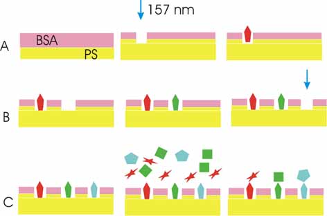
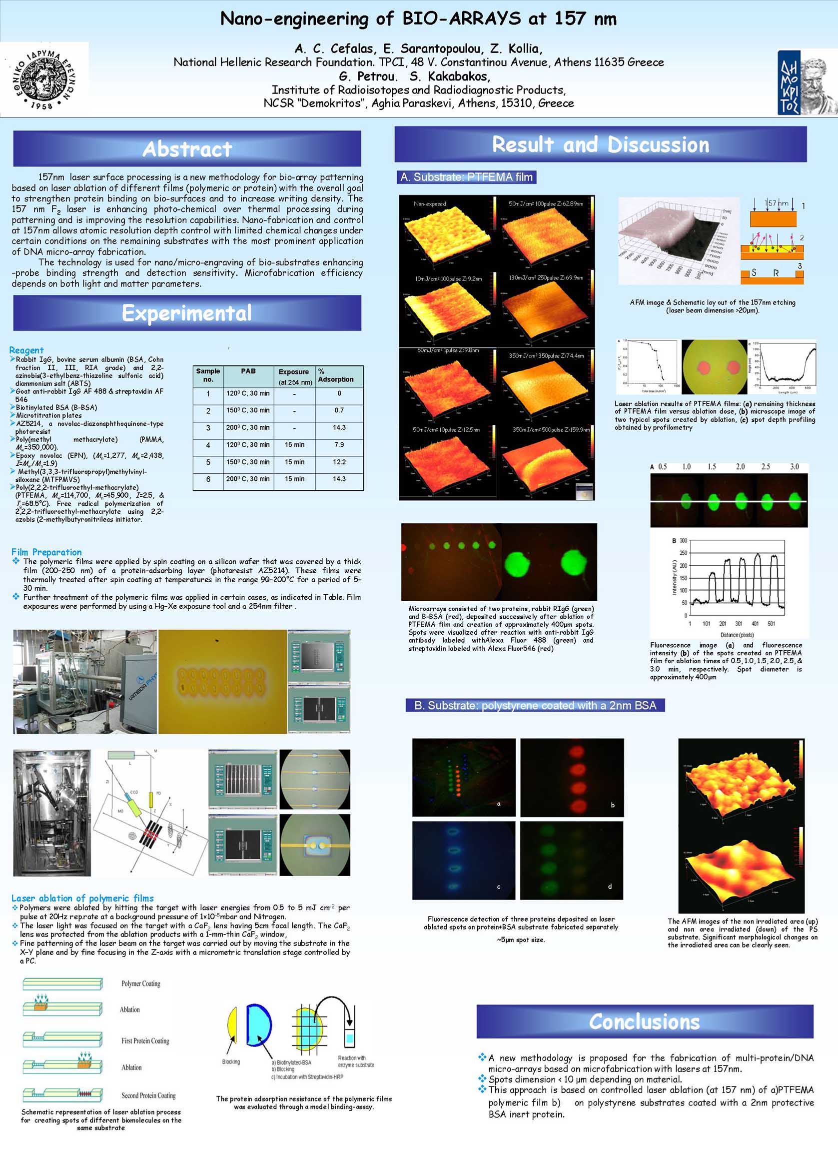
Laser
fabrication bioarrays at 157 nm in three steps.
|
|
The
bovine serum albumin (BSA)-polystyrene (PS) interface layer is laser
photo activated at 157 nm for site selective multiple target-protein
immobilization. The 5-15 nm photon induced interface layer has different
chemical, wetting and stiffness properties than the PS photon processed
surface. The irradiated areas exhibit target-protein binding, followed
by localized probe-target protein detection.
The photon induced chemical modification of the BSA-PS interface
layer is identified by:
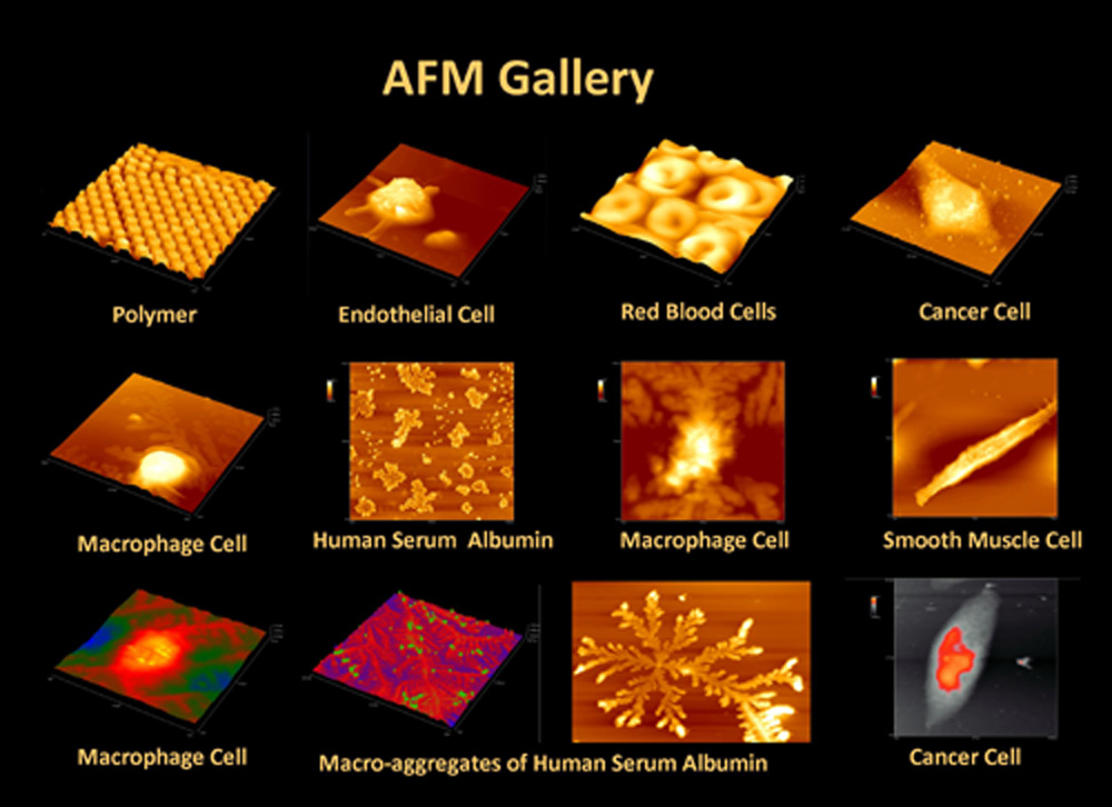
(1) Morphological, imaging and analysis of surface parameters with
Atomic Force Microscopy (AFM).
(2) Spectroscopic shift (4 cm-1), of the amide I group and formation
of new C=N, NH2, C-O, C=O, O-C=O groups following
irradiation, identified with Attenuated Total Reflection Fourier
Transform Infrared (ATR-FTIR) spectroscopy.
(3) The different hydrophilic/hydrophobic and force-distance response
of the bare PS and BSA-PS surfaces.
Near field edge diffraction (Fresnel) fluorescence imaging specifies
the threshold photon energy and the fluence required to detect optically
the protein detection on the photon induced BSA-PS interface layer.
By approximating the Fresnel integrals with analytical functions,
the threshold photon energy and the fluence are expressed as the
sum of zero, first and second order harmonic terms of two characteristic
diffracted modes and they are specified to be 8.73x10⁻⁹
J and 623 Jm-2 respectively. Furthermore, a bioarray of three probe-target
proteins is fabricated with 1.5 micron spatial resolution using
an 157 nm laser microstepper. The methodology eliminates the use
of intermediate polymer layers between the blocking BSA protein
and the PS substrate in bioarray fabrication.
|
|
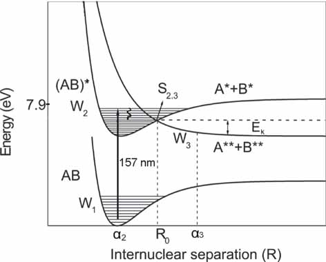
Simplified
schematic diagram indicating the photo dissociation path from an
excited bound electronic state (W2(AB)*), correlated with a repulsive
state (W3(A**+B**)), following VUV irradiation of an organic molecule
(AB).
|
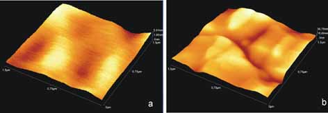
(a) AFM image of
PS surface.
(b) AFM image of irradiated PS surface with 20 laser pulses
|
|
|
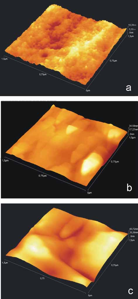
(a)
AFM image of BSA nano composites layered on PS.
|
|
(b)
AFM image of BSA irradiated with 2 laser pulses.
|
| (c)
AFM image of BSA layer irradiated with 20 laser pulses. |
Surface
parameters of bare PS and BSA-PS with the number of laser pulses.
Area RMS of (black) PS and (red)
BSA.
(green) Area average roughness of PS
& (blue) BSA.
(light blue) Average height of PS &
(magenta) BSA.
|
|
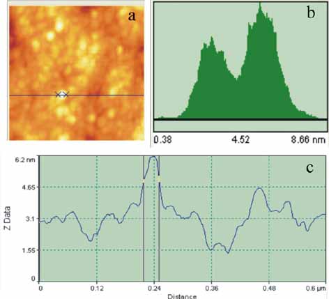
(a)
AFM image of 3-5 nm thick, 30 nm wide non irradiated BSA agglomerations.
(b) Height distribution histogram of the BSA agglomerations consisting
of two broad bands at 3.14 and 5.5 nm respectively for a 600 nm
x 600 nm scan area.
(c) Line profile analysis of BSA agglomerations for a 600 nm scan
where a 30 nm wide protein nano composite is shown.
|
|
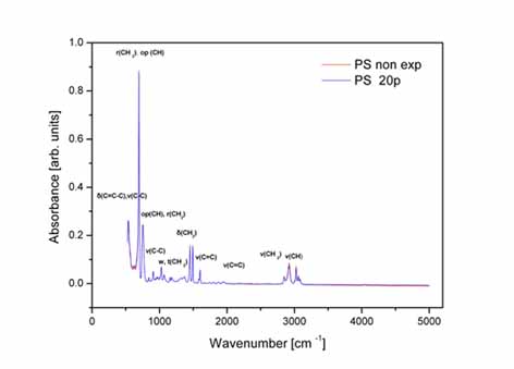 
Left:
ATR-FTIR spectrum of non- irradiated and irradiated with 20 laser
pulses bare PS substrate from 539 to 5000 cm-1.
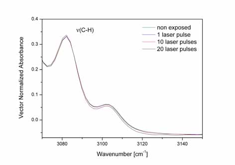
RIght:ATR-FTIR
spectrum of the aromatic C-H stretching vibration mode at 3082.1
cm-1 of the PS substrate irradiated with 1 (1p), 10(10p) and 20(20p)
laser pulses respectively.
|
|
 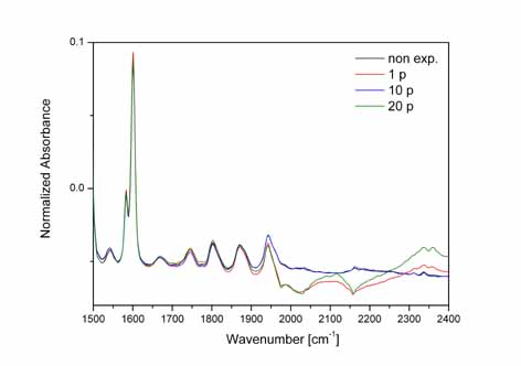
Left:
ATR-FTIR spectrum of the 1701.6 cm-1 band of bare PS with 0(0p),
1(1p), 10(10p) and 20(20p) laser pulses, indicating activation of
the C=O group by atmospheric oxygen after irradiation. The spectra
are normalized using the spectral range from 1490 to 1630 cm-1.
Right:
ATR-FTIR spectrum of the bare PS substrate from 1500-2300 cm-1
irradiated with 1(1p),10(10p) and 20(20p) laser pulses respectively.
The peaks at 1543, 2101.1, 2336.2, 2361 cm-1 correspond
to the presence of NH2 from the scission of
[-N=C=N-] and C-N stressing modes respectively.
|
|
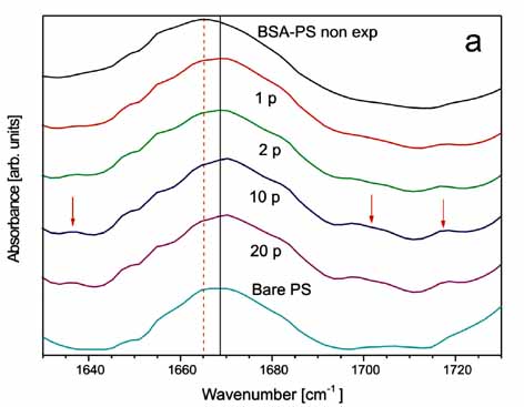 
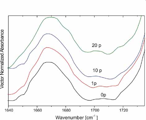
Left:ATR-FTIR
spectrum of the 1635-1700 cm-1 band of BSA -PS following irradiation
with 0 (BSA-PS non exposed), 1(1p), 2(2p), 10(10p), 20(20p) laser
pulses.
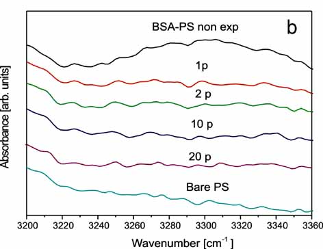
Right:
ATR-FTIR spectrum of the 3200-3370 cm-1 band of BSA-PS with similar
response of the band's peak at 3300 cm-1.
|
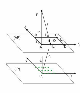
Schematic
lay-out of the diffraction geometry used in this experiment. AP:
aperture plane, IP: Image plane, P: Virtual (apparent) position
of the light source, O: Origin of the coordinate system for aperture
diffraction, P1 : Image recording position.
|
|
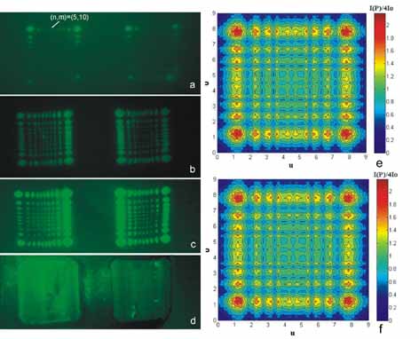
Near
field (Fresnel) edge diffraction pattern following laser irradiation
with a non-focused laser beam with 1 (a), 5 (b), 10 (c) and 20 (d)
laser pulses respectively. Ten diffracted modes are developed along
each one of the perpendicular directions of the two axes in the
image plane.
(e) Simulated 2-D Fresnel edge diffraction pattern along the axes
from the metallic rectangular aperture in agreement with the experimental
images 11(a-c).
(f) First order simulated pattern.
|
|
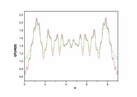
Intensity
distribution of the diffracted mode (n,0) as a function of the dimensionless
parameter u.
|
|

(a)
Schematic lay-out of the near field (Fresnel) edge diffraction pattern
formation following laser irradiation with a non-focused laser beam.
(b) Near field (Fresnel) edge diffraction pattern, [bionytilated-
BSA (target), streptavidin (probe) labelled with AlexaFluor 546
(red)], following laser irradiation with non-focused laser beam
with 2 laser pulses.
(c) Simulated 2-D Fresnel diffraction pattern from the metallic
rectangular aperture.
|
|
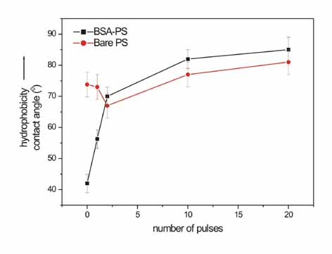
Correlation
between the water contact angle of bare PS (black) and BSA-PS substrates
(red) with the number of laser pulses.
|
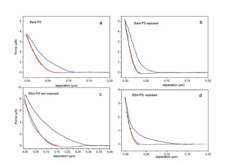
(a)
Force distance response of PS.
(b) Force distance response of PS irradiated with 20 laser pulses.
The Young's modulus of the non-irradiated/irradiated PS areas
is 2.6±0.2 GPa and 11±3 GPa (20 pulses) respectively.
(c) Force distance response of BSA layered on PS.
(d) Force distance response of BSA on PS irradiated with 20 laser
pulses. The Young's modulus of the non-irradiated/ irradiated
BSA-PS system is 1.2±0.3 and 14±5.0 GPa (20 pulses)
respectively.
|
|
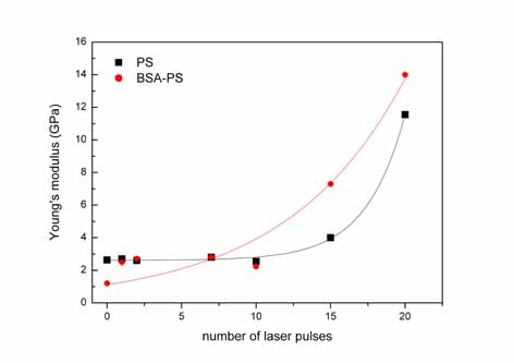
Young's
modulus of the bare PS substrate as a function of the number of
laser pulses.
|
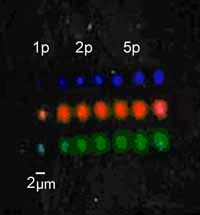
Image
of bio-array with three different proteins (red, green, blue)
fabricated with the automated laser micro-stepper with one, two
and five laser pulses.
|
|
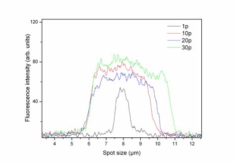 
Left:Intensity
distribution of the fluorescence image taken with a CCD camera across
one micro-spot, from one to thirty laser pulses.
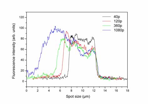
Right:Intensity
distribution of the fluorescence image taken with a CCD camera across
one micro-spot, fabricated with 40 to 1080 different laser pulses.
|
|
Relevant
Publications
- Protein
immobilization and detection on laser processed polystyrene surfaces.
E. Sarantopoulou, P. S. Petrou, Z. Kollia, D. Palles, N. Spyropoulos-Antonakakis,
S. Kakabakos and A. C. Cefalas,
J. Appl. Phys. 110(6), 064309 (2011).
DOI:10.1063/1.3627160
- 157nm laser ablation of polymeric
layers for fabrication of biomolecule microarrays.
A.M. Douvas, P.S. Petrou, S.E. Kakabakos, K. Misiakos, P. Argitis,
E. Sarantopoulou,
Z. Kollia and A.C. Cefalas
Anal. Bioanal. Chem., 381 (5), 1027 (2005).
DOI:10.1007/s00216-004-2985-3
Conference
Presentations
- Nano
-engineering of bio-arrays at 157 nm.
A.C. Cefalas*, E. Sarantopoulou, Z. Kollia,
P. Petrou and S. Kakabakos,
11th Trends in Nanotechnology International Conference, TNT 2010,
Braga,
Portugal, 06-10 September, 2010.
- Nano-engineering
of BIO-ARRAYS with Vacuum Ultraviolet Light.
E. Sarantopoulou, Z. Kollia, A. C. Cefalas, A.
M. Douvas, M. Chatzichristidi, P. Argitis,
K. Misiakos, Z. Petrou and S. Kakabakos,
EMRS 2007, Strasburg France, May 28 - June 1, (2007).
|
48,
Vassileos Constantinou Aven. 11635 Athens, Greece
Tel: +30 210 7273840, Fax: +30 210 7273842, email :ccefalas@eie.gr
|
|


